News & Events
Spanning tree protocol – STP
Hello Guys,
Today we are going to see some interesting topic, You can say an Important Protocol to remember
SPANNING TREE PROTOCOL:
Spanning tree protocol is a layer 2 Protocol being used in Switches and bridges to avoid Loops in the topology.
For better understanding, First we will get to know what is Loops and why we need to avoid them.
SCENARIO:
Look at the diagram given Below.

Here we have a scenario, we have a network with 4 Switches and 1 PC connected to each switch.
For Example We are going to share a Frame from PC1 to PC4
First Step : The Packet Frame will go the Switch 1. It can’t find the destination Address in its SAT table. So it will broadcast it to other Switches.
Second Step : When the Packet Frame reaches to Switch 2 and Switch 3. The Packet Cannot go further Since the PC4 is not Connected with those Switches.
Second Step : Switch 2 and 3 will start Broadcasting the Packets again in all available directions, means to switch 1 from both 3 and 2. These happens in loops all again and again.
This causes a severe resource exhaustion and messy loops in the Network.
The main advantage of this Network is to have redundancy in the network to avoid any breakdown in between the network Nodes
So here we need something to maintain Redundancy and also to avoid this looping. That’s where our STP comes in.
Normally in a Meshed topology in a network, all the Nodes might be having maximum number of connections.
While in STP protocol it should have minimum number of connections.

In STP, we won’t be disconnecting the Physical Connection, instead the Spanning tree protocol will be in play to avoid looping.
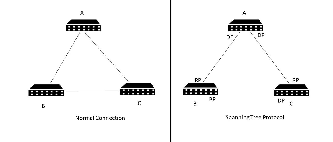
STP selects one Device as the Root bridge. The lowest bridge ID device will be elected as Root bridge and acts as a central point for connection.
From the above picture, if PC B wants to reach A, it can take two paths BCA or BA. The lowest path BA is chosen.
The port from the Switch B will be considered as Root port. Which is the least cost path to the Root Bridge. The port in the Root Bridge will be having Designated Port.
The same Concept applies for Switch C as well. If we see after everything, a non root bridge can have many Designated Ports, but it can have only one Root Port.
In the Other hand Root bridge will be having all the ports as Designated Ports.
The Link between B and C Switches will be blocked by Changing the port Condition to Blocking State in one Device (B ) and a port into Designated port in Switch (C).
So it will be receving the packets, but it will not forward it. HENCE LOOPING GETS STOPPED.
When there is any Disconnection happens between the Nodes. It will automatically get unblocked and started forwarding the Packets.
We will be Discussing about the Spanning Tree protocol also in the Next Blog, Stay Tuned to Learn more about it.
Thanks, Stay Safe and Secure
Author:
Sam Nivethan V J
Security Analyst & Trainer.
To Learn More Subscribe To our Expert Level Courses ECSA or CPENT